Dell QSFP-SR1.2-100G Compatible 100G QSFP28 SR1.2 Transceiver Module
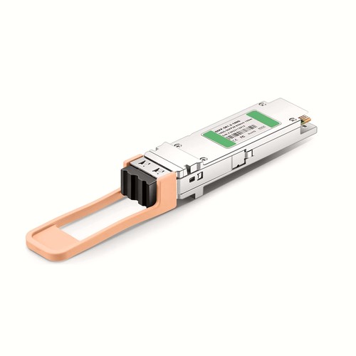
This Dell QSFP-SR1.2-100G compatible transceiver provides 100G connectivity in a hot-swappable QSFP28 package. Its optical design operates at 850/910nm for up to 70m on OM3 / 100m on OM4 / 150m on OM5, using Duplex LC. Complete parameters and related OEM references help data-center designers evaluate optical reach, rack integration and host compatibility together.
OEM Part Number: QSFP-SR1.2-100GHT Part Number: QSFP-SR1.2-100G
Product Highlights
- Compatible alternative to Dell QSFP-SR1.2-100G
- 100G connectivity at 106.25 Gbps
- Optical wavelength: 850/910nm
- Specified reach: 70m on OM3 / 100m on OM4 / 150m on OM5
- Duplex LC / MMF interface
- Digital diagnostic monitoring: Supported
- Operating temperature: -10 to 60 ℃ (14 to 140°F)
Specifications
| HT Part Number | QSFP-SR1.2-100G |
|---|---|
| Manufacturer | HT |
| Form Factor | QSFP28 |
| Max. Data Rate | 106.25 Gbps |
| Wavelength | 850/910nm |
| Max. Cable Distance | 70m@OM3/100m@OM4/150m@OM5 |
| Connector | Duplex LC |
| Media | MMF |
| Transmitter Type | Broadcom/AFCD-V7 |
| Receiver Type | PIN |
| TX Power | -6.2dBm~4dBm |
| Minimum Receiver Power | -8.2dBm |
| Power Budget | 2dB |
| Receiver Overload | 4dBm |
| Power Consumption | ≤4W |
| Extinction Ratio | >3dB |
| DDM/DOM | Supported |
| Commercial Temperature Range | -10 to 60 ℃ (14 to 140°F) |
| Modulation (Electrical) | 4x 25G-NRZ |
| Modulation (Optical) | 2x 50G-PAM4 |
| CDR (Clock and Data Recovery) | TX & RX Built-in CDR |
| Inbuilt FEC | KP4 FEC |
| Packaging Technology | COB Packaging |
| Core Size | 50um/125um |
| Protocols | QSFP28 MSA and IEEE 802.3bm CAUI-4 |
Applications and Optical Link Design
This coherent interface is suited to data-center interconnect, metro transport and managed DWDM links where the host platform supports the stated modulation and FEC modes. Design the optical line around the actual launch power, receiver range, OSNR requirement and span loss; the stated reach is not a substitute for a link-budget calculation. Use matching coherent modules and the appropriate DWDM channel plan at both ends.
Before deployment, check the host port type, supported data rate and firmware requirements. The 100G interface configuration must match the remote equipment; sharing a QSFP28 housing alone does not make two transceiver types interoperable.
For this coherent interface, document the wavelength plan and modulation or FEC settings before commissioning. Measure span loss and verify adequate OSNR. Interoperability depends on compatible coherent modes as well as form factor, so another coherent part number must not be substituted without engineering review.
Quality Assurance and Packaging
Quality control covers the optical or electrical interface, host identification and operating link. The verified unit is then individually protected and cartoned. Customer references, rack groups and project packing lists can be added for volume orders.
Optical Acceptance, Diagnostics and Handling
For this model, the specified transmit-power range is -6.2dBm~4dBm; the stated optical power budget is 2dB. During commissioning, record the host diagnostic readings after the link has stabilized and compare them with those limits. DOM values are useful operational indicators, but they do not replace calibrated optical measurements when a link is marginal. Investigate unexpected loss through connector inspection, cleaning and a channel measurement before replacing the module. Diagnostic monitoring is listed as Supported. Before every insertion, keep dust caps in place until the patch lead is ready, avoid touching the optical end face and use an appropriate inspection and cleaning procedure. Do not look into an active optical interface.
Data-Center Optical Design and Airflow
Select the module by optical standard, reach and rack layout. Check the complete fiber channel, including panels and connectors, and keep dense bundles from blocking front-panel airflow. Account for listed power consumption and preserve enough space to remove a module without disturbing adjacent links. For this model, the principal parameters are data rate 106.25 Gbps, wavelength 850/910nm, rated reach 70m on OM3 / 100m on OM4 / 150m on OM5.
Ordering Information
Use QSFP-SR1.2-100G as the compatibility cross-reference and QSFP-SR1.2-100G as the HT ordering identity. Keep other reaches or wavelength directions on separate order lines. Neutral labels, customer packaging and project-specific compatibility review are available on request.
Dell Compatibility and Factory Testing
Factory verification starts with the expected QSFP-SR1.2-100G identity and finishes with an operating host link. EEPROM data, diagnostic visibility and the stated optical parameters are assessed together. Equipment model, hardware revision and software release can be reviewed before dispatch where platform behavior is uncertain.
Frequently Asked Questions
Is this an original Dell transceiver?
No. It is an HT-manufactured compatible alternative for equipment that specifies QSFP-SR1.2-100G, not an original Dell-branded module.
Which fiber and connector are required?
Use Duplex LC with MMF. The specified maximum reach is 70m on OM3 / 100m on OM4 / 150m on OM5, subject to fiber quality and total link loss.
Can it be mixed with another wavelength or reach version?
Only when the two ends share the same optical standard, wavelength plan and supported data rate. Check the exact part numbers and link budget rather than relying only on the module form factor.
Shipping and Lead Time
Standard configurations normally ship within one to three working days, with production lead times confirmed for larger quantities. International courier, air freight and sea freight are available; customer courier accounts and nominated forwarders are accepted.
Fiber Optic Cables
Fiber Optic Transceivers
Featured Products
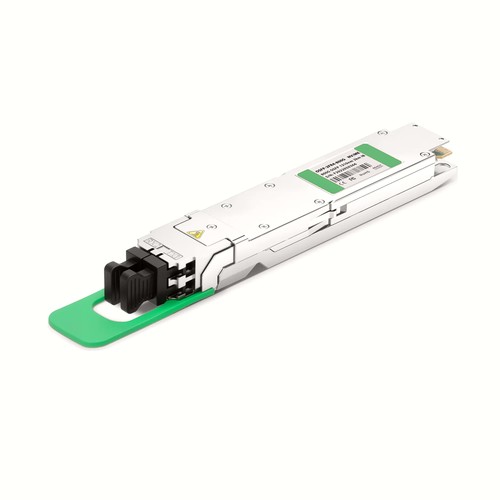 800G TransceiversOSFP and QSFP-DD modules for AI data center networks
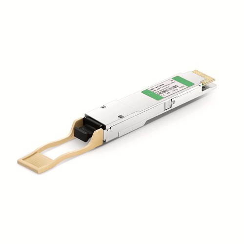 400G QSFP-DDSR8, DR4, FR4 and LR4 modules and cables
 100G QSFP28SR4, CWDM4, LR4 and ER4 transceivers
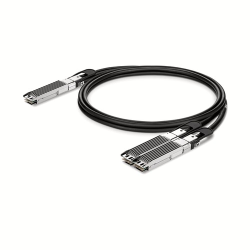 DAC CablesDirect attach copper cables from 10G up to 800G
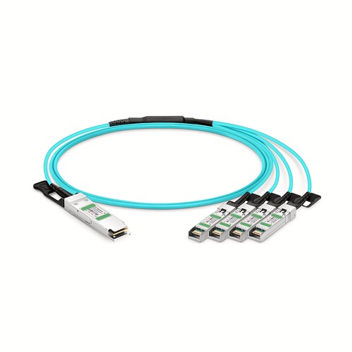 AOC CablesActive optical cables for rack-to-rack links
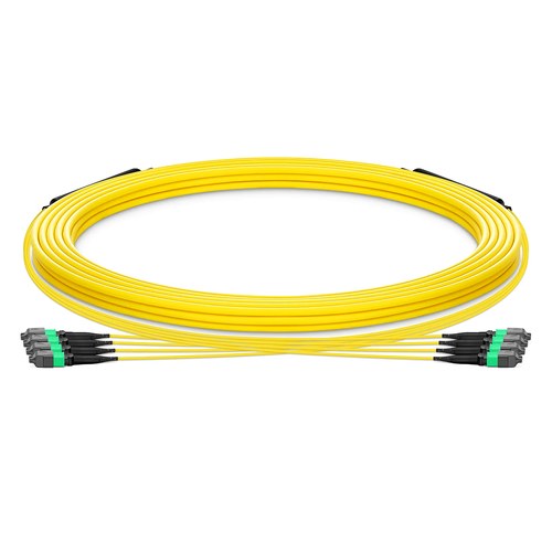 MTP/MPO Trunk Cables8F to 144F multi fiber trunk and harness cables
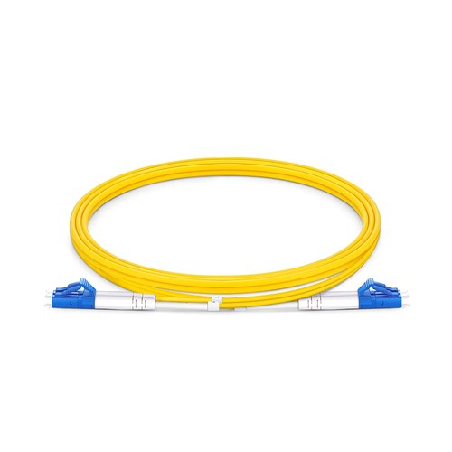 Fiber Patch CablesOS2, OM3, OM4, OM5 jumpers with LC, SC, FC, ST connectors
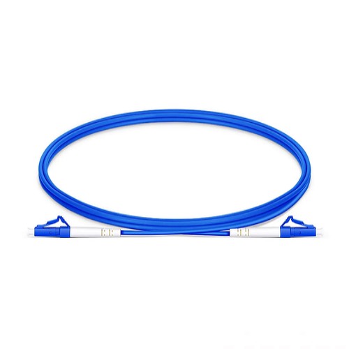 Armored Patch CablesStainless steel tube protected fiber patch cords
UAE Fiber Optics
UAE office: Abu Dhabi,Al khaleej Al Arabi
Factory add: ZYT industrial area, Shiyan, Baoan district, Shenzhen, China 518000
Popular Products
- Fiber Optic Patch Cord
- Fiber Optic Pigtail
- Fiber Optic Attenuator
- Fiber Optic Patch Panel
- Fiber Optic Adapter